
I used to think that a home theater was only possible in some massive dream home but turns out it can be done inexpensively with a little creativity. For this project I’ve designed a remote controlled projector lift that can be mounted directly to the ceiling. Is this excessive? Yes. Is there an easier solution? Probably. Do I care? Nope.
The Concept:
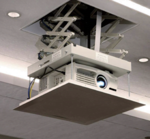
The idea is to base the design off of common commercial solutions that are used in classrooms and conference centers. Most of these feature a similar design that involves moving a mounting plate for the projector up and down via a cable system and motor. For rigidity these assemblies also include scissor style bracers on the sides to limit the sway of the projector while hanging. This allows for a compact size that can extend large distances.
The total travel distance that I need for my place’s average height ceiling is no where near that of the commercial versions, so the same cable system isn’t really necessary. Instead, I’m modifying the design by using a lead screw to drive a scissor lift in place of the cable spool.
Hardware:
There was a lot of trial and error that went into the design of each aspect of the final assembly to get a version that works. A lot of that probably could’ve been avoided by buying metal parts, but I was curious to see just how capable 3D printed parts could be in a machine application like this; so the entire mechanical assembly and housing are actually printed. I won’t go through every iteration and failed attempt but here’s a brief summary.
Scissor Lift:
The main challenge with the scissor lift was the design of connecting pins capable of withstanding the load without breaking and, preferably, be easy to assemble. The first attempt was a pin split with a gap down the middle and a lip at the end that allows for the pin to snap into its mating hole. This took a few iterations to get right. While I really liked how well this design worked at first, it unfortunately wasn’t robust enough to withstand the loading from the weight of the projector. It turned out that this first version of the pins did not hold up well under even limited cycles.

For the second version I quickly realized that the pin would need to be solid all the way through to stand a chance at resisting the shear force of the projector load. This meant that I needed a different way to secure the pins in place. The solution to this was creating snap rings to secure around the other side of the pin once it’s in the corresponding mating hole. Since there is effectively little to no load acting on the snap ring; a split ring only a few layers thick is more than sufficient to hold the assembly together.
This new design has held up great to daily use over months. Not only do the finished scissors work great for the lift, but they’ve also turned out to be a fun desk fidget.
Lead Screw:
I’m using a lead screws for a couple of reasons. For one they allow for the translation of the motor’s rotational motion to linear motion. Another major benefit is that the screw can drive the nut, but the nut can’t back-drive the screw due to the lead angle of the threads. That means I’m able to adjust the scissors to a specific height without worrying about the weight of the lift causing the lift to slowly lower.
The screw interfaces with a special wing nut that extends out symmetrically to the two scissors on opposite sides of the lift. The lead screw will also need to interface with the motor shaft. Since the threaded shaft is already going to be printed out I decided to build the coupling directly into the part with a make-shift setscrew. While threading plastic is technically possible, those threads would not hold under any real torque applied to the motor. To fix this I made a coupling with a fitting for a square nut and paired that with a machine screw that secures on the flat of the shaft.

The last important thing to note is that the friction between the leadscrew and wing nut is higher than what would be optimal. This is no surprise given that they are both the same printed plastic. To alleviate this issue, and prevent an annoying squeal, the screw needs to be lubricated. I had some grease for the linear rails on the 3D printer laying around that I found works well and I reapply when I start to hear a noise.
The biggest headache on this part was to design the tolerance on the male and female threads to a point that they are both printable and functional. Too tight and the friction puts a strain on the motor, too loose and the two sides of the lift may become uneven.
Housing:
The housing is made up of three parts; the base which serves as the main mounting point of all the other pieces, and two side panels that act as the guides for the scissors. I haven’t talked about it yet but the base needs to support all of the electronic components as well. To accommodate those I’ve built in a number of features that allow me to both align and secure the components easily. The motor is secured with machine screws to a built in bracket while the other lighter items are secured using some VHB tape or hot glue.

Electronics:
The Brains:
There’s no complicated computations required for this project so a basic microcontroller is all that is needed. That’s good news because size is also limited in this design so I’ve chosen to use an Arduino Nano Every which offers more than enough peripheral connection pins for the lift. This will connect to the motor controller, limit switches, and IR sensor.
Like I mentioned at the beginning, the projector lift is going to be remote operated since it’s mounted directly to the ceiling. I had a spare IR sensor and remote laying around that I connected and wrote some code to process the inputs for up and down to the buttons of my choosing. Later I realized that the other remotes that we were using (i.e. the roku and projector) were sending IR signals that the sensor was picking up; so if there’s a remote with any useless buttons this would be perfect to use.
The last piece of the controls is to ensure that the motor doesn’t drive the wing nut to crash into the base if the wrong input is given on the remote. Two opposing limit switches are placed inside the base to let the microcontroller know if the screw has turned too far and needs to stop. Before you ask, the locations of the switches in the photo below is just for sizing, not the final location.

Motor:
Last but not least is the motor. You’ve probably already figured out from the photos above that I’m using a stepper motor here. A stepper motor is perfect for this because it allows me to define exactly how many revolutions I need in order to have the projector stop at the perfect height. This is dependent on the pitch of the threads on the lead screw and the travel of the scissor lift but can easily determined through some testing.
Nothing too special here in my selection. With a low profile NEMA motor, the base was able to easily accommodate the spare motor controller that I had laying around.
Assembly:
Now the fun part. With everything printed and electronics working, it’s time to put it all together.

I’m really happy with how well this thing works. It’s fun and easy to setup for a movie or show at anytime and makes our room really feel like a theater. After subjecting the lift to daily use for over 6 months, the parts have held up really well and the lift continues to function great.
To complete the setup; I also picked up some stereo desktop speakers to place on our end tables which also had an included subwoofer. These ran me less than $50 and add to the experience even more.
Want to build your own?
If you’re looking for a fun, practical project to work on to improve your home then please consider checking out my guide below. It includes all the 3D print files, code, and steps needed to complete the project headache free!
I spend a lot of hours making these projects and would really love your support. Thanks!

Home Theater Projector Lift – Guide and Files
Ever dream about having a home theater for your place? It’s easier than you may think. A ceiling mounted projector lift to complete any home theater.
This purchase includes all the 3D printing models, code, parts list, and guide to build your own projector lift.
See the project write-up HERE.
Pingback: A DIY scissor lift for home theater projectors | Arduino Blog